Since the winter of 2021, I have been a “lucky” owner of a 2013 Peugeot 208 GTi. As any 22-year-old, I absolutely loved driving my new machine, fueling the expensive 100-octane gasoline, ripping it around local windy roads, enjoying every second of it while it worked.
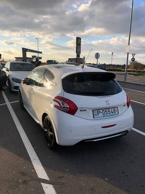
Of course, it didn’t take too long, and I started spending my hard-earned money on maintenance and upgrades. After buying new tires and fixing all most of its issues, I became quite unhappy with the built-in sat-nav. The original unit was a SMEG unit manufactured by Magnetti Marelli, and it was the most basic one. Not only was it an absolute UX nightmare (who tf thought it would be a good idea not to have a main menu but to switch between “radio”, “sat-nav”, “phone” screens), it didn’t have CarPlay or Android Auto, and the latest map update was from 2020. As a hacker and a geek, I started looking for alternative head-units. I didn’t want any Chinese Android unit, as those don’t function completely well, and look completely wrong when built-in. Luckily, I knew that Peugeot in the latest facelift versions has used the NAC/RCC units manufactured by Continental (NAC) and Bosch (RCC). Those have Apple CarPlay and Android Auto, and luckily, there already is a guy selling complete conversion kits for not that much money. These units also need to get coded, but that guy can code it for you, the only thing left is to install it. After it arrived, I installed it, cracked the digitizer of the screen, so re-installed it with a new digitizer, and everything worked.
The Problem
There are two things that have always bothered me since, which I thought are not an easy thing to fix and can be potentially interesting to look at as part of “self-learning”.
1. The missing oil temperature
A GTi is a performance machine. It has a 1.6-liter turbocharged 4-cylinder engine with 200 horsepower. When pushing the car to its limits, it is very important, also considering the age and mileage of the car, to look at the temperatures of the car. These engines are known to run hotter than other competitors like a Ford Fiesta ST or a VW Polo, but the car communicates the temperatures very poorly with the driver. There is only one gauge for the coolant temperature, which always shows 95°C if the temperature is within the range of 90-105°C. The oil temperature is not shown in any way with the driver, so you are left out to estimate if the engine is already warm, just based on the coolant temperature, and you have no way to check it when you are pushing it. Might be 110°C, might be 120°C, no one knows.
The hacker inside me thought, maybe I can hack the instrument cluster to show me the oil temperature. How hard can that be?
2. The corrupted messages between new head-unit and instrument cluster
One thing I noticed after changing the head-unit was that when showing radio/music data or navigation data on the instrument cluster’s center display, the center display is not showing the information properly.
- As for music, when playing music through CarPlay, the center display is stuck on either last radio station, or is showing “no music playing”.
- As for navigation, when driving on streets containing non-ASCII characters, there are empty boxes instead of the non-ASCII characters.
This was another thing that pushed me into hacking the instrument cluster.
The Plan
My plan is to investigate into the CAN communication between the instrument cluster and the rest of the car. With my background in automotive security, I had some idea how to proceed with both of the problems:
- I assume there is a UDS service providing oil temperature, so my plan is to find out how to get it, read it out using some ESP32 or similar, and send it to the head-unit’s display, either as a custom warning or replacing data I don’t really need when pushing the car, e.g., music data.
- This one should be easier. I assume, the head-unit display in my car has a different (outdated) firmware compared to the facelift versions. I can try to flash a newer firmware to my display, however I want to avoid that, as the original displays are not easy to buy and I could do some serious damage to it. The better option to me was to simply “translate” the CAN messages to something the display can understand.
- For music, I know that the original head-unit had an “iPod” input and that was also supported by the display. As I am using an iPhone anyways, I am fine with “translating” the CAN messages of “playing xyz using CarPlay” to “playing xyz using iPod” which the display hopefully will understand.
- For navigation, I will simply “translate” all sat-nav related CAN messages to only contain ASCII characters by converting all of the UTF-8 text to ASCII.
The Setup
Now it is end to “storytelling” and we finally get our hands dirty. To proceed with hacking, we have to prepare some stuff.
Hardware
As I live in a city and don’t have a garage (heck, I don’t even have a fixed parking place, have to park randomly on the street), there was no option to hack things directly in my car. I need to use my car on weekly basis, so removing the instrument cluster also isn’t really feasible, and I also don’t really want to mess up my instrument cluster, as it is a GTi one, again not really cheap to get a new one (and a new one is a mess to install, more on that later).
The decision was to buy a second instrument cluster and build a “test bench” at home to test out things. As mentioned, GTi instrument clusters are not that cheap to buy (when I was looking, they were over $100). Luckily, the GTi instrument cluster is more or less the same as any other instrument cluster of that generation 208. I bought on eBay an instrument cluster with center display for around $45, the only differences was the color scheme, and the center display being monochrome polychrome, instead of full color like on my instrument cluster:
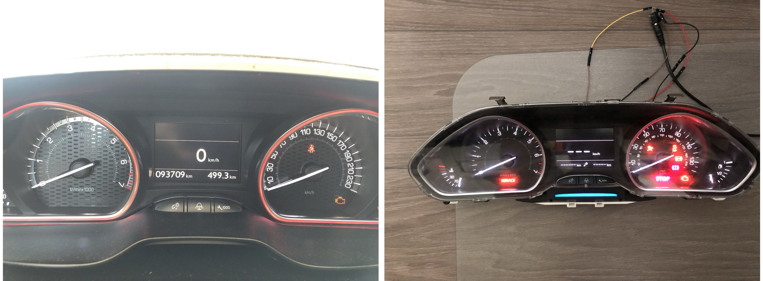
Instrument Cluster
The instrument cluster is a standard 208 instrument cluster with (MATT) matrix polychrome center display. The instrument cluster and center display each have their own connector. Luckily, I found a good article on the internet by SnowdenLabs who has already found out some stuff, including the pinout, we can use regarding the instrument cluster. As for the center display, by quick google search I found also the pinout for that.
Instrument Cluster Pinout
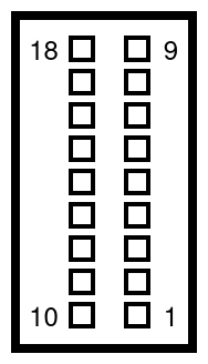 |
|
| 10 | +12V |
| 15 | GND |
| 7 | CAN High |
| 9 | CAN Low |
As for the rest of the pins, I currently don’t know what these are for. According to my knowledge, all functions are controlled via CAN Bus, but the cable bundle going to the connector contained more than 4 wires, so I assume they must be doing something.
Matrix Center Display Pinout source
 |
|
| 1 | +12V |
| 2 | CAN Low |
| 3 | CAN High |
| 4 | |
| 5 | |
| 6 | GND |
Pins 4 and 5 are unoccupied, the connector going into the display is wired only by 4 wires.
Power
As for power, I used a simple universal 12V power supply from Amazon.
Wiring
This will be a very controversial part of my setup, because I didn’t strictly stick to the specification of CAN bus, as I wanted to keep everything rather simple. Therefore, I used a prototyping breadboard to connect everything together. I created 4 lines on my breadboard, one line with +12V, one GND line, one CAN High line, and one CAN Low line. According to CAN bus spec, CAN Bus should be a pair of twisted wires. However, in my case I connected everything using (non-twisted) jumper wires. This can cause problems, but on those few centimeters my bench CAN bus is running on, it should not make huge problems. Also, in my case I don’t have to fulfill any safety criteria, so it’s not a big issue if a few CAN frames corrupt. Following are a few pictures of my fancy wiring setup:
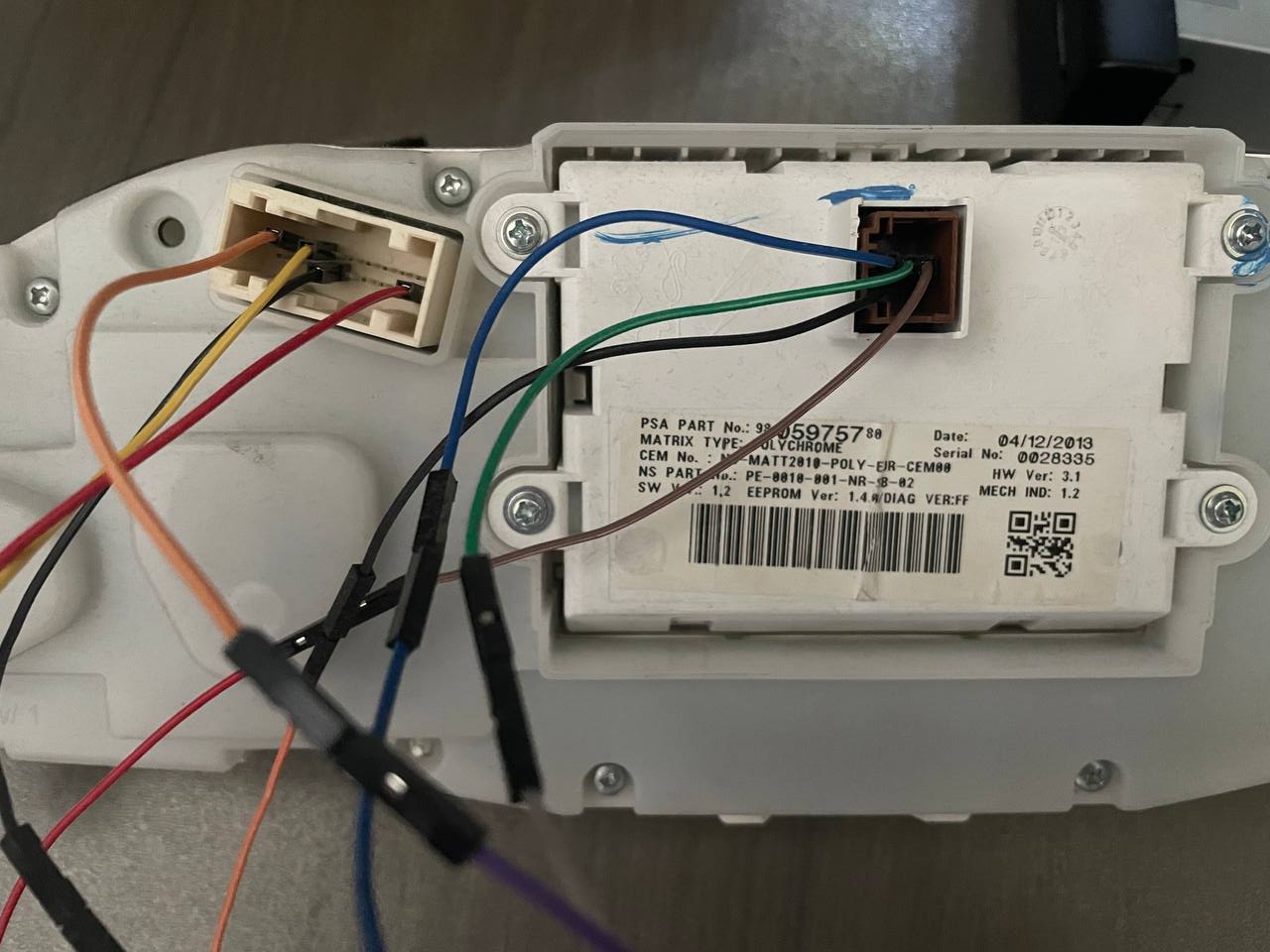
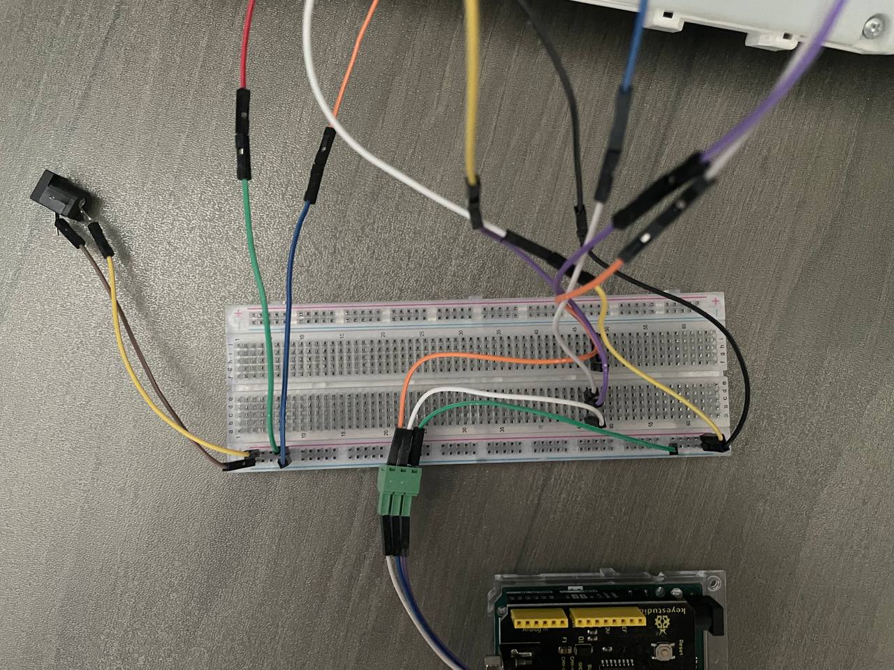
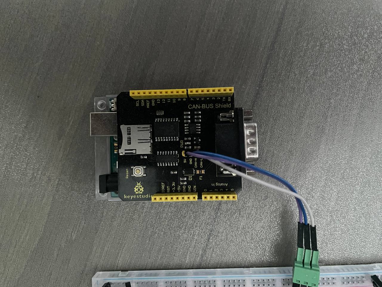
NOTE: To check your wiring, you can press the 🔧/000 button on the instrument cluster. If everything is wired right, you should see an information about your service interval on the center display. If you see the information, that means your CAN bus is wired correctly and the instrument cluster is communicating with the center display.
CAN Adapter
To interact and sniff the CAN bus I bought 2 devices I wanted to use. I bought an UCAN board on Amazon that was supposed to be compatible with candlelight firmware, however I could not manage to make this board work in any way. Till this day I have no idea what went wrong, I tried multiple firmware versions, multiple configs, with termination and without, I always was receiving just one CAN frame and then the interface stalled. If you have any idea how to make the UCAN board work, please contact me on ado4007(at)gmail.com, I’ll be very happy about any input.
I also bought a keyestudio CAN bus shield for Arduino Uno, originally to interact with the car, however I was able to set it up with SocketCAN on Linux to sniff and interact with the CAN bus, more on that in later section.
Software
After having everything hardware-wise connected, it was time to look on the software side. I am using Linux (Ubuntu 24.04) on my personal laptop and I can only recommend using Linux just for the sake of canutils (SocketCAN). It is very easy to use and sniff/interact with the connected CAN bus, or connect it further with other software. I already mentioned, I am using a CAN bus shield for Arduino Uno that “converts” “CAN to USB”. I used following sketch that allowed me to use canutils through the Arduino.
There are several important steps you have to complete to be able to succesfully sniff/interact with the CAN bus of PSA vehicles.
- PSA CAN Bus for instrument cluster and co. has a baud rate of 125k, this is rather unusual, but it is the case for PSA vehicles. To adjust for this, you need to edit the line 11 of the sketch from:
int g_can_speed = CANSPEED_500; // default: 500kto
int g_can_speed = CANSPEED_125; // default: 500k - Running following commands:
$ sudo slcan_attach -f -s6 -o /dev/ttyACM0 $ sudo slcand -S 1000000 ttyACM0 can0 $ sudo ifconfig can0 up - You are ready to go, you can try
$ candump can0and you should see CAN frames.
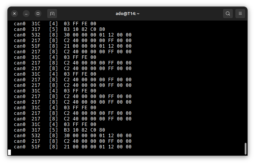
To cleanup you just run:
$ sudo ifconfig can0 down
$ sudo killall slcand
There are many programs that allow you to analyze CAN bus, I recommend checking out following GitHub repo that has also lots of other useful tools listed. I decided to use SavvyCAN, however this can change during my research, so take this with a grain of salt.
SavvyCAN Setup
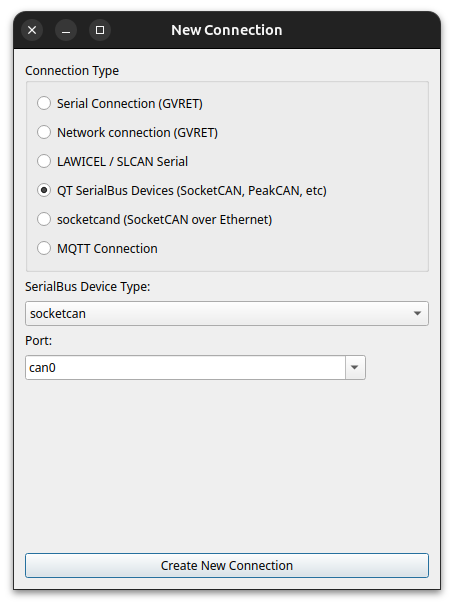
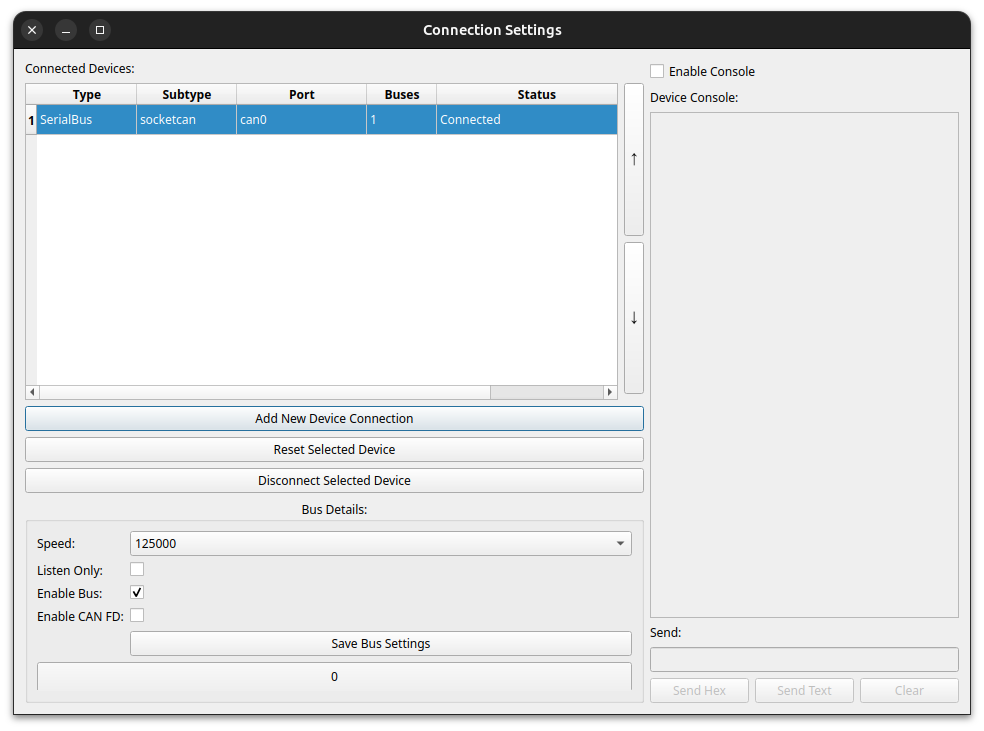
After you download SavvyCAN you can open it and go directly into Connection->Open Connection Window and you will get to the connection settings. Here we need to setup our connection to SocketCAN device can0.
- You click on
Add New Device Connection - Select
QT SerialBus Devices (SocketCAN, PeakCAN, etc) - Choose
can0as device type - Click
Create new connectionand you should already see CAN Frames in the main window (assuming you got everything hooked-up)
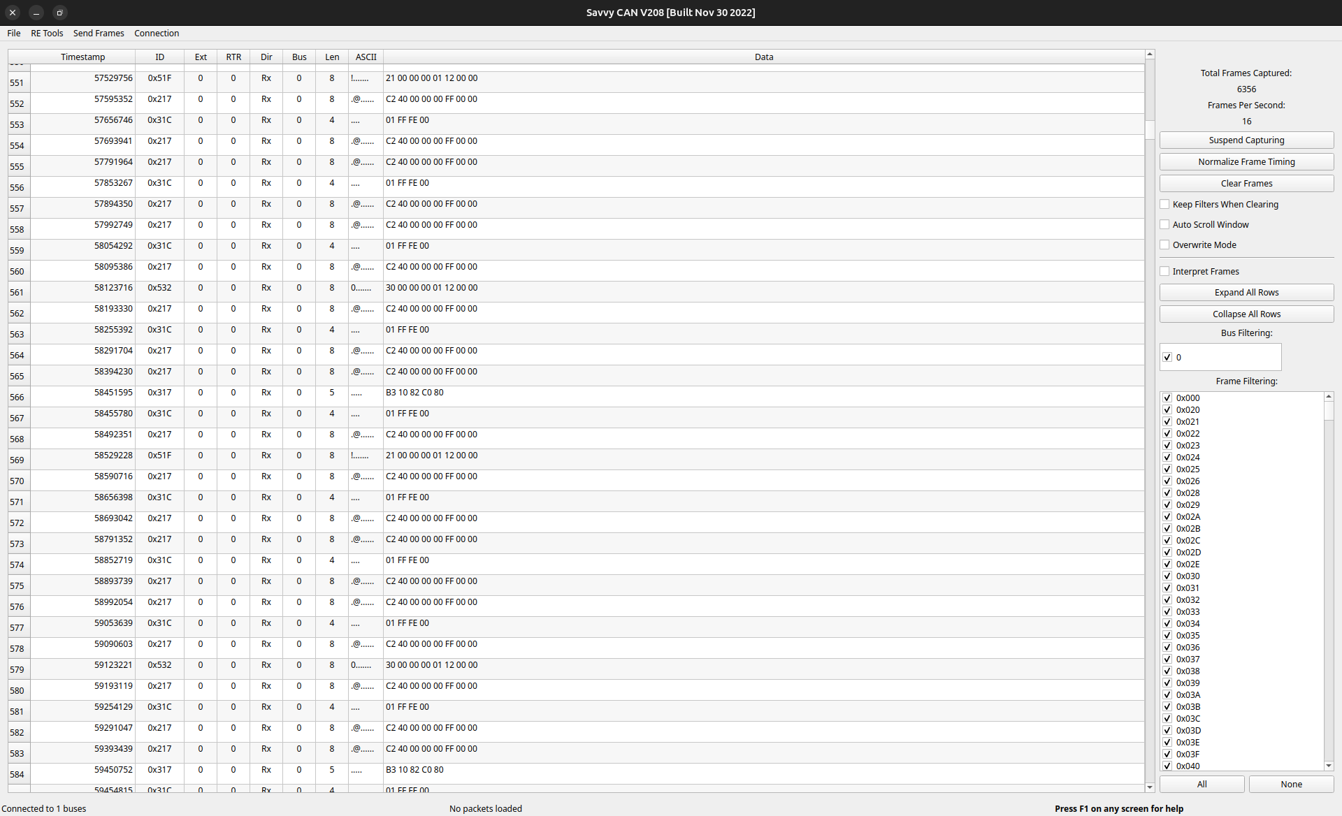
When we have everything done correctly, we can now even try if we can interact with the CAN bus, let’s try some fuzzing using SavvyCAN (Send Frames->Fuzzing). We setup the fuzzer to send something randomly on IDs 0x20 to 0x500 and look if we get something changing on the instrument cluster.
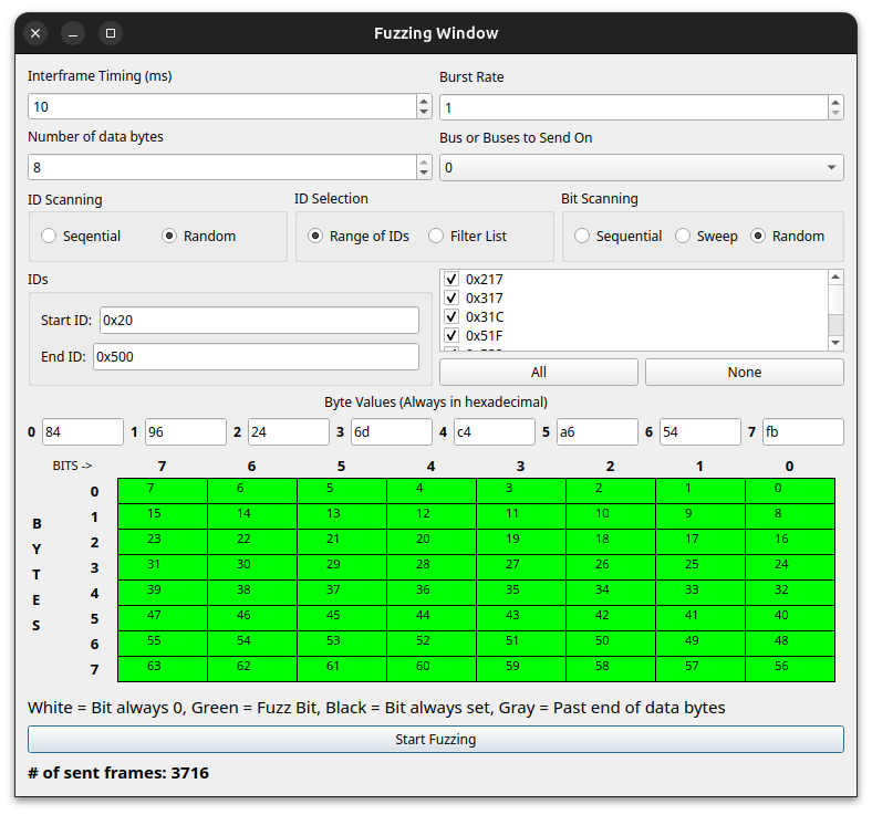
Hopefully you got some warning messages, or the needles moved, or something funny happened (my display changed to Chinese, noice). If not, check your cables, maybe something disconnected on your setup.
To be continued…
This is everything for part 1. We got everything set up so we can play with the instrument cluster. In the next part I will be fuzzing the instrument cluster to find what IDs belong to what data, I will be looking into UDS, and in part 3 I will be sniffing CAN bus in my GTi.
Thanks for reading, stay tuned for the other parts!
